


Light Intensity and Solar Energy Detector with Tilt Sensor
August 21, 2020
Navigation Bar
Apply Theme
- Introduction
- Keywords
- Brands
- Hardware
- Software
- Description
- Step 1: Designing and Soldering the Light Intensity and Solar Energy Detector with Tilt Sensor PCB
- Step 2: Calculating Solar Energy Approximately
- Step 3: Programming the Arduino Nano
- Connections and Adjustments
- Features
- Demonstration
- Project GitHub Repository
- Schematics
- Code
- Custom assets
- See on other platforms
- Related projects
Evaluate the possible magnitude of solar energy by the light intensity in a given direction to charge batteries efficiently.
Keywords
Hardware
- [1]JLCPCB Custom PCB
- [1]Arduino Nano v3
- [4]10mm Photoresistor
- [1]Tilt Sensor (Mercury Sensor)
- [1]Buzzer
- [4]5mm Red LED
- [4]5mm Yellow LED
- [4]5mm Green LED
- [13]220Ω Resistor
- [5]1K Resistor
- [1]Power Jack
Software
Description
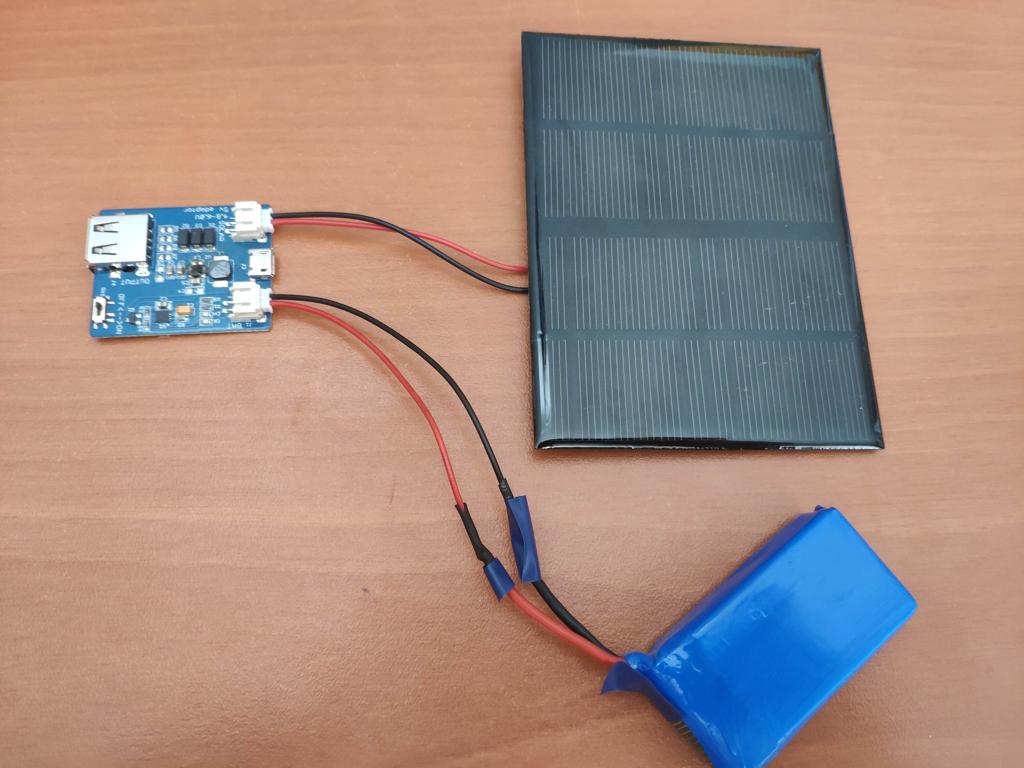
For charging batteries with solar panels to run some devices in my home office, I have placed the solar panels according to my predictions on the best possible location without gathering reliable data. Therefore, I pondered a cheap and easy-to-use mechanism to determine the perfect location for solar panel charging depending on the light intensity in a given direction. I am able to charge batteries more efficiently and sustainably with this device than before because the amount of energy generated by a solar panel is closely related to the amount of solar radiation. Hence, I used light intensity values as a substitute to calculate the magnitude of solar energy approximately. You can inspect the formula I used to calculate solar energy below.
After running the code to calculate solar energy with light intensity values gathered by 10mm photoresistors, I conducted experiments with batteries and my solar panel to determine thresholds for performance levels of solar charging: Low, Moderate, High. And, to show the performance levels, I used different LED colors - red (Low), yellow (Moderate), green (High) - for each direction.
Not surprisingly, it is crucial to place the device perpendicular to detect light intensity accurately, so I used a tilt sensor (mercury sensor) to check if the device moves into a tilted position. And, to notify the user, when the device moves into a sloping position, I added a buzzer to the device.
After completing my design on a breadboard and testing the code, I designed a PCB (Light Intensity and Solar Energy Detector with Tilt Sensor) with a unique circular shape to create a flexible and easy-to-use device supporting four directions.
Huge thanks to JLCPCB for sponsoring this project.

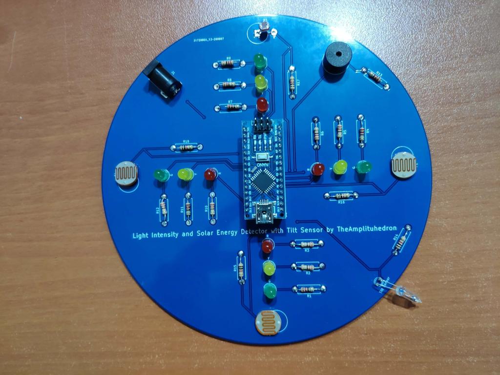
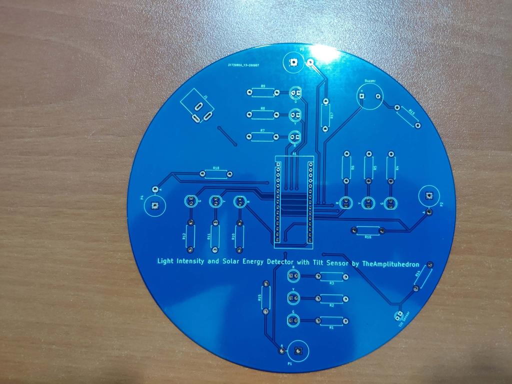
Step 1: Designing and Soldering the Light Intensity and Solar Energy Detector with Tilt Sensor PCB
I designed the Light Intensity and Solar Energy Detector with Tilt Sensor PCB by using KiCad. I attached the Gerber file of the PCB below, so if you want, you can order this PCB from JLCPCB to use your solar panels more efficiently and sustainably as I did :)

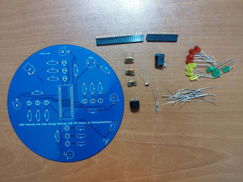
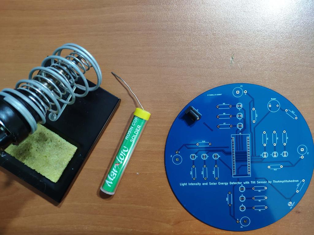
First of all, by using a soldering iron, I attached headers, 220Ω resistors, 1K resistors, 10mm photoresistors, the power jack, 5mm red LEDs, 5mm yellow LEDs, 5mm green LEDs, buzzer, and the tilt sensor (mercury sensor).
Component list on the PCB:
A1 (Headers for Arduino Nano)
P1, P2, P3, P4 (10mm Photoresistors)
Buzzer (Buzzer)
Tilt Sensor (Tilt Sensor)
R (5mm red LEDs)
Y (5mm yellow LEDs)
G (5mm green LEDs)
R1, R2, R3, R4, R5, R6, R7, R8, R9, R10, R11, R12, R13 (220Ω resistors)
R14, R15, R16, R17, R18 (1K Resistors)
J1 (Power Jack)


Step 2: Calculating Solar Energy Approximately
[ E = A * r * H * PR ] is the formula I used for calculating the magnitude of solar energy approximately, where:
A is the area of the solar panel,
r is the efficiency,
H is the average solar radiation,
and PR is the performance ratio or coefficient (generally 0.75).
// Define the solar panel (SP) specifications which differ amid different brands. So, change these variables with that of your solar panel.
#define SP_area 0.0088
#define SP_efficiency 6.2
#define SP_coefficient 0.75

float Solar_Panel_Energy(float Area, float Efficiency, int Radiation, float Coefficient){
  // Calculate the possible magnitude of solar energy by using the light intensity values as a substitute for radiation.
  float Energy = Area * Efficiency * Radiation * Coefficient;
  return Energy;
}
Do not forget to change solar panel specifications - area, efficiency, and performance ratio - which may differ amid solar panel brands.
To calculate the possible magnitude of solar energy, I used light intensity values as a substitute for solar radiation in the formula.
Of course, this method does not provide exact solar energy values but an indicator to determine thresholds (Low, Moderate, High) for detecting solar charging performance in a given direction.
Note: I determine the thresholds for each level by conducting tests with my solar panel: I observed time passed in given light intensity and estimated solar energy values to full-charge a 3.7V LiPo battery.
Step 3: Programming the Arduino Nano
- Define indicators (red, yellow, green) for each direction.
- Define LDR pins for each direction to gather light intensity values.
- Define the buzzer pin and the tilt sensor pin.
- Define the solar panel (SP) specifications, which differ amid different brands. So, change these variables with that of your solar panel.
- Define thresholds by experimenting.
- In the get_Light_Intensity() function, gather light intensity data from photoresistors.
- In the Tilt() function, get notified if the device moves into a sloping position.
- Initiate threshold detection (Low, Moderate, High) for each direction.
- In the Indicate_Thresholds() function:
- Print the selected direction with its solar energy value.
- Adjust threshold indicators (LEDs) according to solar energy values for each direction.


Connections and Adjustments
// Connections
// Arduino Nano :
//                                direction_1_LOW
// D4  ---------------------------
//                                direction_1_MODERATE
// D3  ---------------------------
//                                direction_1_HIGH
// D2  ---------------------------
//                                direction_2_LOW
// D7  ---------------------------
//                                direction_2_MODERATE
// D6  ---------------------------
//                                direction_2_HIGH
// D5  ---------------------------
//                                direction_3_LOW
// D8  ---------------------------
//                                direction_3_MODERATE
// D9  ---------------------------
//                                direction_3_HIGH
// D10 ---------------------------
//                                direction_4_LOW
// D13 ---------------------------
//                                direction_4_MODERATE
// A4  ---------------------------
//                                direction_4_HIGH
// A5  ---------------------------
//                                Buzzer
// D11 ---------------------------
//                                Tilt Sensor
// D12 ---------------------------
//                                direction_1_LDR
// A0  ---------------------------
//                                direction_2_LDR
// A1  ---------------------------
//                                direction_3_LDR
// A2  ---------------------------
//                                direction_4_LDR
// A3  ---------------------------
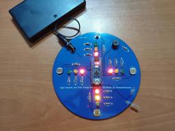
After finishing and uploading the code to the Arduino Nano, I attached it to the board through headers.

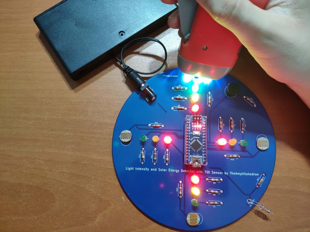
Features
1) Display the estimated magnitude of solar energy for each direction on the serial monitor.

2) For each direction, observe the performance of solar charging via indicators adjusted according to solar energy thresholds (levels):
Red - Low
Yellow - Moderate
Green - High

3) Get notified if the device moves into a sloping position to charge batteries more efficiently with perpendicular beams.

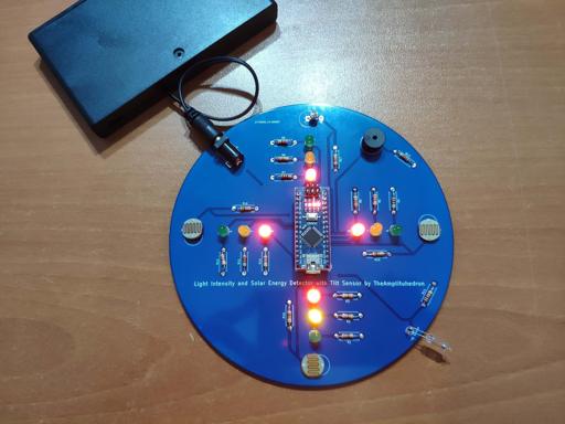
Demonstration
Project GitHub Repository
The project's GitHub repository provides:
- Code files
- PCB design files (Gerber)
Schematics


Code
Custom assets
See on other platforms
Related projects
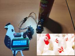
Arduino RTC Bird Feeder v2.0 for Poultry Conditioning
Feed the poultry in quotidian routine to condition them to improve egg production and hatching process.
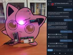
Jigglypuff IoT Carbon Dioxide and Dust Monitor (Tracker) w/ Telegram
Based on Arduino Nano RP2040 Connect, display the dust density (mg/m3) and the carbon dioxide (CO2) density (ppm) via a Telegram bot.

Arduino Plant Water Management System w/ BME280
Track the total volume of water spent and evaluate approximate evaporation rates by temperature, humidity, and pressure to prevent water overuse.

TV Series / Anime New Episode Release Date Notifier
Get informed when new episodes of your favorite shows are on release with their opening songs via Nano 33 IoT and Raspberry Pi.

RFID Desk Lamp with RGB Color Scheme Lock
Enhance a dilapidated desk lamp w/ insipid features into an RFID enabled one w/ personalized RGB scheme lock via Arduino.