


Bluetooth Mobile Remote Lamp with Weather Station
March 20, 2020

Navigation Bar

Apply Theme
- Introduction
- Keywords
- Brands
- Hardware
- Software
- Description
- Step 1: Designing the Mobile Remote Lamp PCB
- Step 2: Developing an Android Application (Remote Lamp)
- Step 3: Programming Arduino Nano
- Features
- Connections
- Conclusion
- Demonstration
- Project GitHub Repository
- Schematics
- Code
- Custom assets
- See on other platforms
- Related projects
Control your room lighting system and display weather information via specifically developed Android application and a uniquely designed PCB.
Keywords
Hardware
- [1]Arduino Nano
- [1]HC-06 Bluetooth Module
- [1]DHT11 Module
- [1]I2C LCD Screen (16, 2)
- [1]L298N Motor Driver
- [2]DC Motor
- [1]9V Battery
- [1]2-Way Relay
- [1]RGB LED
- [1]5mm Yellow LED
- [1]5mm Blue LED
- [1]5mm Green LED
- [1]5mm Red LED
- [7]220 ohm resistor
Software
Description
I have created an electronics project named Remote Lamp two years ago, as my new room lighting system with adjustable RGB, LEDs, and some joyful features controlled by a TV remote control. However, I decided to improve the mentioned project since it has irritating redundant wiring due to the LCD screen connections and deficiencies in the user interface due to the TV remote control. So, I took my nascent idea of remote control of my room lighting system and turned it into a mobile remote lighting system controlled by an Android application developed by me. And, to get rid of the redundant wiring and add more features with limited pins on Arduino Nano, I designed a PCB (Printed Circuit Board) named Mobile Remote Lamp with Weather Station V2.0, which includes all built-in component connections.
Inspect my previous project.
PCBWay.com sponsored this project by providing me with the mentioned PCB (Mobile Remote Lamp with Weather Station V2.0) without a shipping cost. You can inspect their service from here.

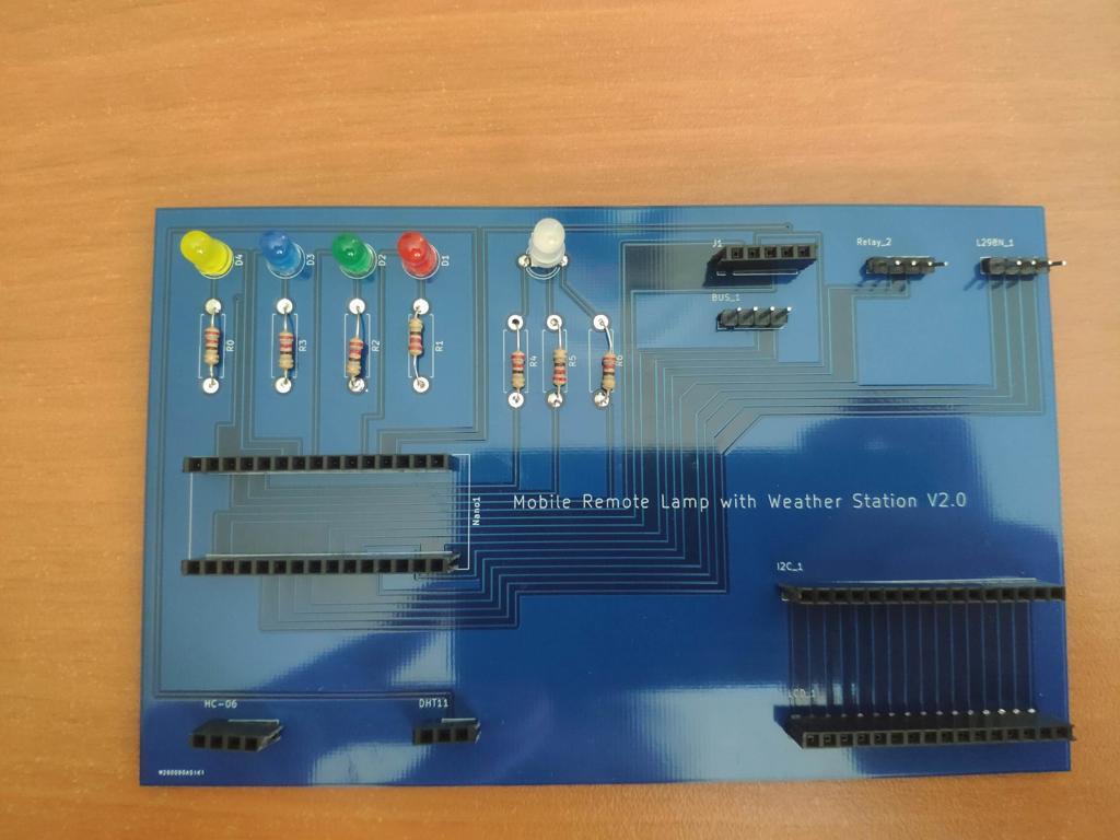
Step 1: Designing the Mobile Remote Lamp PCB
I designed a PCB for this project on KiCad, named Mobile Remote Lamp and Weather Station V2.0. All components and products I used in this project have built-in connections and pin outputs on the board. I used Arduino Nano as the center of the board due to its efficiency as compared to other alternatives. Check out the pin output instructions to see all supported components by the board.
You can inspect the board schematic on Schematics.
Also, you can buy and inspect my PCB design on PCBWay from here :)

Pin Output:
Pins are representing Arduino Nano pin output for supported components on the board.
 PCB Connector                   Components

 HC-06                           HC-06 Bluetooth Module
 D4  --------------------------- TX
 D5  --------------------------- RX
 5V  --------------------------- 5V
 GND --------------------------- GND

 BUS_1                           I2C LCD Screen (BUS)
 A4  --------------------------- SDA
 A5  --------------------------- SCL
 5V  --------------------------- 5V
 GND --------------------------- GND

 DHT11                           DHT11 Temperature and Humidity Sensor
 D2  --------------------------- Signal
 5V  --------------------------- 5V
 GND --------------------------- GND

 L298N_1                         L298N DC Motor Driver
 A0  --------------------------- IN_1
 A1  --------------------------- IN_2
 A2  --------------------------- IN_3
 A3  --------------------------- IN_4

 Relay_2                         2-Way Relay
 D12 --------------------------- IN_1
 D13 --------------------------- IN_2
 5V  --------------------------- 5V
 GND --------------------------- GND

 RGB1                            RGB LED
 D9  --------------------------- R
 5V  --------------------------- 5V
 D10 --------------------------- G
 D11 --------------------------- B

 D4                              5mm Yellow LED
 D8  --------------------------- +

 D3                              5mm Blue LED
 D7  --------------------------- +

 D2                              5mm Green LED
 D6  --------------------------- +

 D1                              5mm Red LED
 D3  --------------------------- +

 J1 Connector (Spare Pins)
 A6
 A7
 VIN
 3V3
 GND
Warning: Under the Relay_2 connector on the board, I connected A6 and A7 pins as the output pins; but they cannot be used as outputs due to the chip settings. So, I used the spare pins - 12 and 13 - on the J1 connector as the output pins for the 2-Way Relay Module, and therefore A6 and A7 pins on the Relay_2 connector became spare pins.

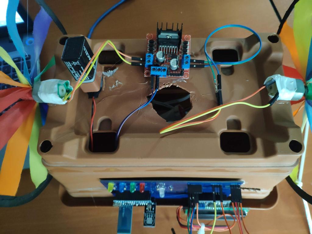
Soldering:
After the fabrication process and delivery of my PCB design, I soldered male and female connectors, 220 ohm resistors, LEDs, and an RGB on the board to attach all components properly.


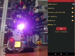
Step 2: Developing an Android Application (Remote Lamp)
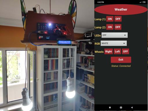
I wanted to control my lighting system and its joyful features using my mobile phone :) Hence, I developed an Android application named Remote Lamp with a user-friendly interface on MIT App Inventor 2. It transmits specific characters to the HC-06 Bluetooth Module for each command as explained in Commands. You can inspect the building blocks of the application by zooming in to the blocks figure.
You can download the application (Remote Lamp) on Google Play :)
For those who want to download it directly on their phone, I leave the application .apk file in Downloads.

Commands:
- Clicking the Weather button, activate the Weather Screen - transmits 't'.
- Clicking Lamp (1) buttons, turn on or off Lamp (1) - transmits '5', '7'.
- Clicking Lamp (2) buttons, turn on or off Lamp (2) - transmits '6', '8'.
- Choosing options in the LEDs slider, turn on or off yellow, blue, green, red LEDs - transmits '0', '1', '2', '3', '4'.
- Choosing options in the RGB slider, change the RGB color as red, green, blue, yellow, purple, cyan, white, or off - transmits 'r', 'g', 'b', 'y', 'p', 'w', 'o'.
- Clicking Wheels buttons, turn right and left wheels or stop them - transmits 'a', 's', 'd'.
- Open the notification bar by clicking the Exit button:
- Clicking the Home Screen button, activate the Home Screen - transmits 'h'.
- Clicking the OK button, close the application and disconnect Bluetooth.

Step 3: Programming Arduino Nano
Download the required libraries:
LiquidCrystal_I2C | Download
DHT | Download
- Include the SoftwareSerial library to communicate with the HC-06 Bluetooth Module.
- Initiate the bluetooth module. Connect the defined RX pin (4) to the TX pin on the bluetooth module.
- Include DHT.h library.
- Define the dht object.
- Include LiquidCrystal_I2C and Wire libraries to run I2C module.
- Set the LCD address to 0x27 for a 16 chars and 2 line display.
- Define custom characters for the LCD.
- Activate the bluetooth module and initiate the DHT11 module.
- You do not need to take any further action to define SDA and SCL pins in Wire library due to embedded SDA and SCL settings on Arduino Nano.
- Define the home screen settings.
- Adjust the RGB color to white at the home screen initializing.
- In getDataFromDHT11() function, get weather information - temperature (celsius / fahrenheit) and humidity - using built-in functions.
- Wait until the DHT11 module is ready.
- If the Weather Screen is requested by a command ('t'), print the weather information generated by the DHT11 Temperature and Humidity Sensor.
- If the Bluetooth module is available and receiving characters from the Android application, execute the requested command depending on the received character.
- In the changeColor() function, adjust the color of the RGB LED using the analogWrite() function.
Bonus: By uncommenting the changeBluetoothSettings() function, change the Bluetooth module defaults settings using AT Commands - Name: Remote Lamp, Password: 1234, Baud Rate: 9600.


Features
Before trying the following features, pair the HC-06 Bluetooth Module with your phone to connect to the board (Mobile Remote Lamp with Weather Station V2.0) with the application (Remote Lamp).


1) Connect to the HC-06 Bluetooth Module.


2) Adjust the color of the RGB LED on the board.


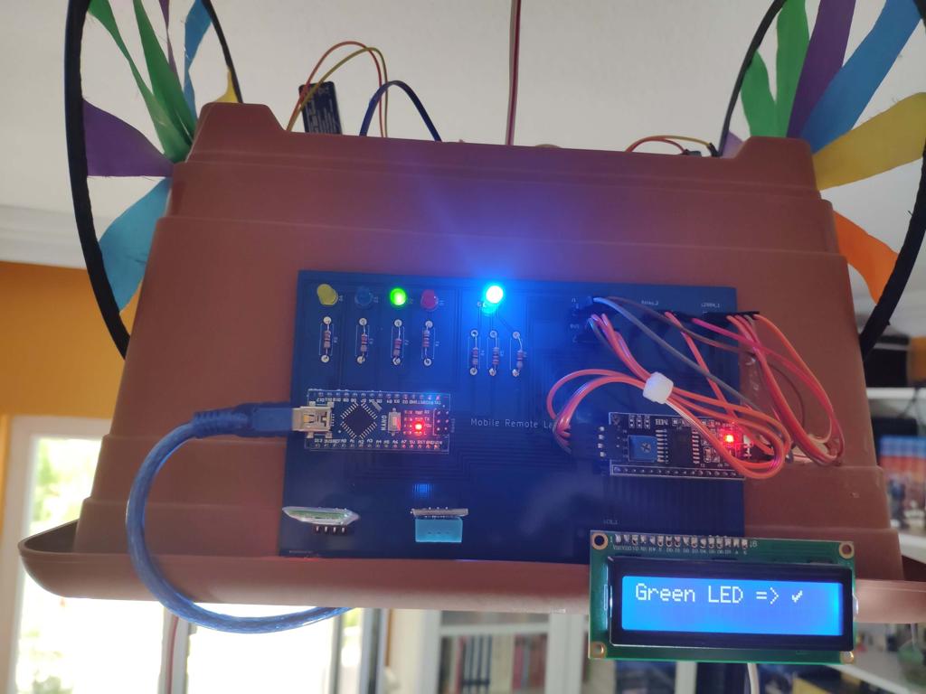
3) Turn on or off yellow, blue, green, red LEDs on the board.


4) Turn on or off the Lamp (1).


5) Turn on or off the Lamp (2).


6) Activate the turning wheels attached to the L298N Motor Driver - right and left.


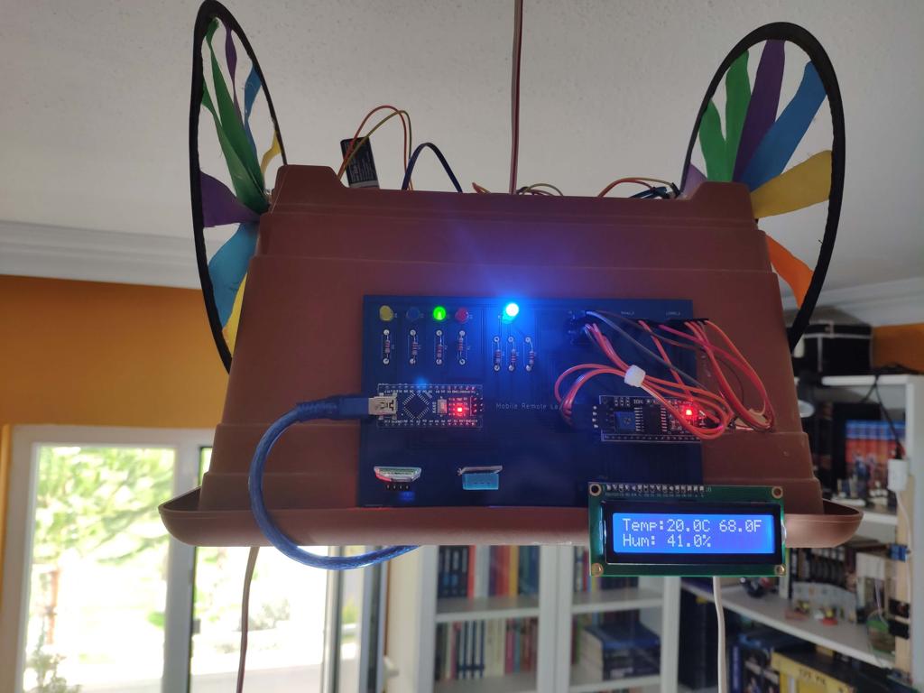
7) Activate the Weather Screen to display the weather information generated by the DHT11 Temperature and Humidity Sensor - temperature (in celcius and fahrenheit) and humidity.


8) Open the notification bar to close the application or return to the home screen.


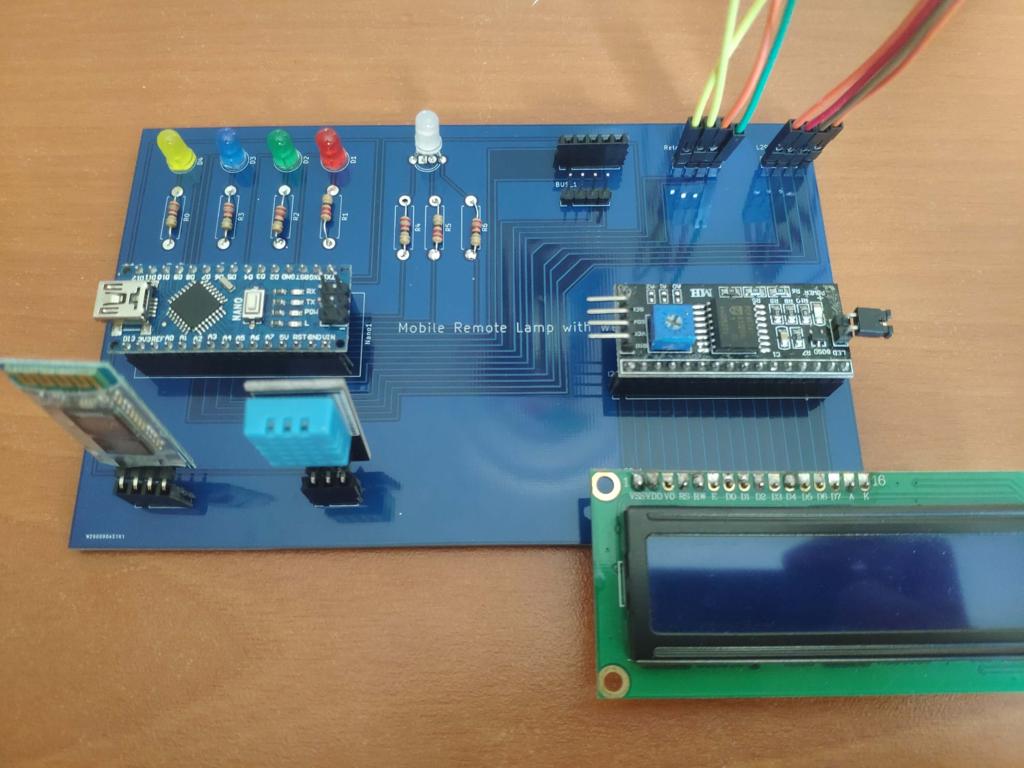
Connections
Connect all supported components to the corresponding connector on the board (Mobile Remote Lamp with Weather Station V2.0).


Now, you can create your lamp design using the finished apparatus :)
I used a dilapidated flower pot from my previous project and affixed the board on it with the turning wheels by using a hot glue gun.
I connected bulb plugs to a 3-Way socket adaptor and used my old phone battery charger to supply Arduino Nano on the same adaptor.
To supply the turning wheels (attached to DC motors), I used a 9V battery.


Conclusion
After completing each step, I fastened the contraption to the ceiling and connected the power cable :)


Demonstration
Project GitHub Repository
The project's GitHub repository provides:
- Code files
- Mobile application APK file (Android)
- PCB design files (Gerber)
Schematics


Code
Custom assets
See on other platforms
Related projects
Bluetooth-enabled Snowman Weather and Air Quality Gift Card
Via the gift card's Android application, adjust its RGB eye color and display weather and air quality information on the ST7789.

Arduino Plant Water Management System w/ BME280
Track the total volume of water spent and evaluate approximate evaporation rates by temperature, humidity, and pressure to prevent water overuse.

Mobile Water Level Tracker
View the water integrity and level of selected areas on your Android phone by using an HC-06 Bluetooth module to make an irrigation system.
Multi-Model AI-Based Mechanical Anomaly Detector w/ BLE
Apply sound data-based anomalous behavior detection, diagnose the root cause via object detection concurrently, and inform the user via SMS.
BLE Mobile Star Wars Remote Lamp w/ Weather & Gas Station
I built this luminous lighting system and developed an Android app to control its various features and display real-time weather & gas data.