


The Magnetic Field and RGB Tester
November 19, 2017
Navigation Bar
Apply Theme
Observe the magnetic field integrity and polarity in the air with the 3144E Hall effect sensor. Also, adjust the RGB LED colours easily.
Keywords
Hardware
- Arduino Uno[1]
- 3144E Magnetic Hall Effect Sensor[1]
- LCD Screen(16,2)[1]
- Potentiometer[3]
- Single Turn Potentiometer(10K)[1]
- Buzzer [1]
- SparkFun Pushbutton [2]
- RGB Led [1]
- Resistor 220 ohm [5]
- Jumper Wires [1]
Software
Description
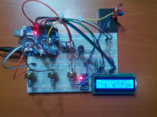
I have needed a device to detect the magnetic field in the air when I was working with the magnets and DC motors so I created a basic device which shows the magnetic field integrity and the polarity in the air with the 3144 Hall Effect Sensor. After that, I decided to add an RGB LED test system into the project because I had been getting bored with setting up the circuit for Arduino every time.

The Magnetic Field Integrity and Polarity Test
Sometimes you might want to detect the polarity of the magnet or sometimes you might want to know whether your DC motor works or not without making a circuit for it. And you must have a device that can detect the magnetic field integrity and polarity for the jobs like these.

The Magnetic Field and RGB Tester which is a basic magnetic field detector allows you to make all these jobs basically.
By clicking the second button, the magnetic field integrity is revealed as a pointer and the polarity can be detected by observing the movements of the pointer.


RGB Led Test
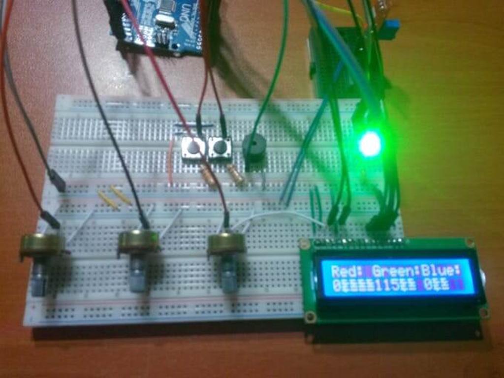
Three different potentiometers so you can adjust each LED in an RGB (Red, Green, Blue) which allows you to test your RGB LED easily.
Also, you can see the results on LCD screen when you adjust the number from 0 to 255 by clicking the first button. Moreover, you can use the device as an RGB picker and create special colours.
It is the easiest way to test an RGB LED.


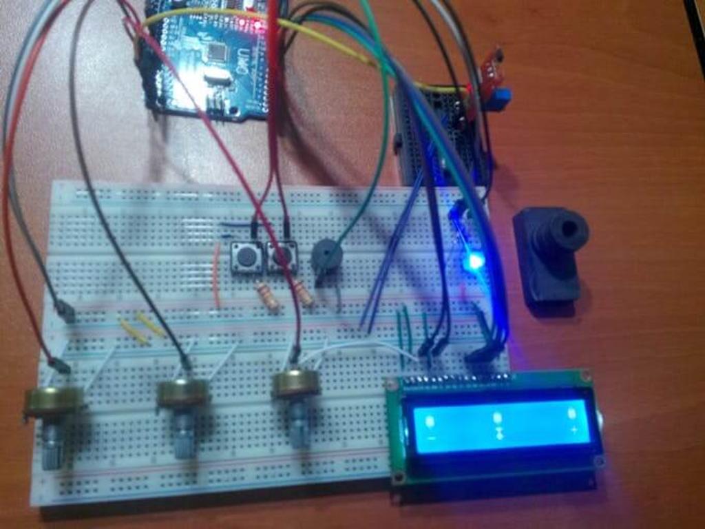
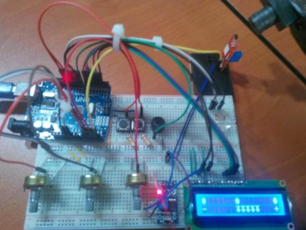
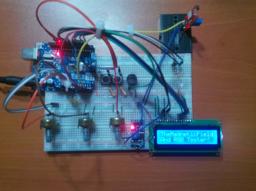
Connections
// Arduino UNO
//                                 LCD Screen
// Pin 2  -------------------------rs
// Pin 3  -------------------------en
// Pin 4  -------------------------d4
// Pin 5  -------------------------d5
// Pin 6  -------------------------d6
// Pin 7  -------------------------d7
//                                 Buzzer
// Pin 8  -------------------------
//                                 RGB
// Pin 9  -------------------------
// Pin 10 -------------------------
// Pin 11 -------------------------
//                                 Button(1)
// Pin 12 -------------------------
//                                 Button(2)
// Pin 13 -------------------------
//                                 Potentiometer(1)
// Pin A1 -------------------------
//                                 Potentiometer(2)
// Pin A2 -------------------------
//                                 Potentiometer(3)
// Pin A3 -------------------------
//                                 3144E Hall Effect Sensor
// Pin A4 -------------------------


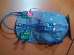
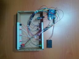
After making all the connections correctly, I stuck the Arduino Uno to the top of the first breadboard with a silicon gun and connected an old single turn potentiometer to the LCD screen by using a soldering iron.


Videos
Project GitHub Repository
The project's GitHub repository provides:
- Code files
Schematics

Code
See on other platforms
Related projects
IoT Tesla Coil and Cooling Fan on the Localhost
Develop a web application in PHP and JavaScript to control a Tesla coil and a cooling fan via Arduino Nano 33 IoT. Get information from the Tesla Coil Controller without needing to click to a classic submit button.
Jar Temperature Detector and Cooling Fan
If the temperature measured by DS18B20 is above the predefined threshold, it turns the fan on automatically unless the piezodisk is pressed.
RFID Desk Lamp
Supersede your old desk lamp with a new one controlled by an RFID tag or card and personalize it with an RGB color pattern to turn it off.
Mobile Weather Station Being Powered by Solar Energy
Get the weather information through an Android app constantly and use the solar energy generated by the PV panel to charge devices.
Create a People Counter controlled by an Android app
Make a people counter that detects the number of people who enter the room using lasers and LDRs and control it with an Android app.